Embark on a journey into the realm of fork and blade connecting rods, where precision engineering meets relentless power. These vital components, the unsung heroes of countless machines, play a pivotal role in converting reciprocating motion into rotary motion, enabling the seamless operation of engines and other mechanical systems.
Join us as we delve into the intricacies of fork and blade connecting rods, exploring their types, materials, manufacturing processes, applications, and maintenance.
Fork and Blade Connecting Rod
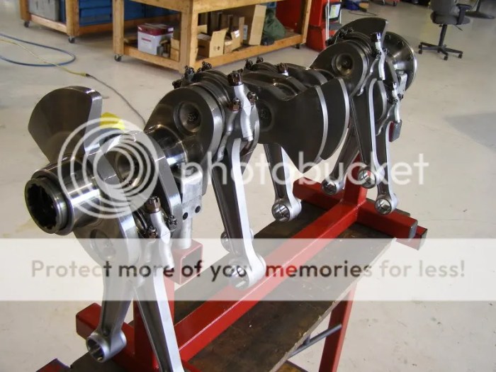
In the realm of mechanical engineering, the fork and blade connecting rod stands as a pivotal component, orchestrating the seamless transmission of power within reciprocating engines. Its primary function lies in establishing a crucial link between the piston and the crankshaft, facilitating the conversion of linear piston motion into rotational crankshaft motion.
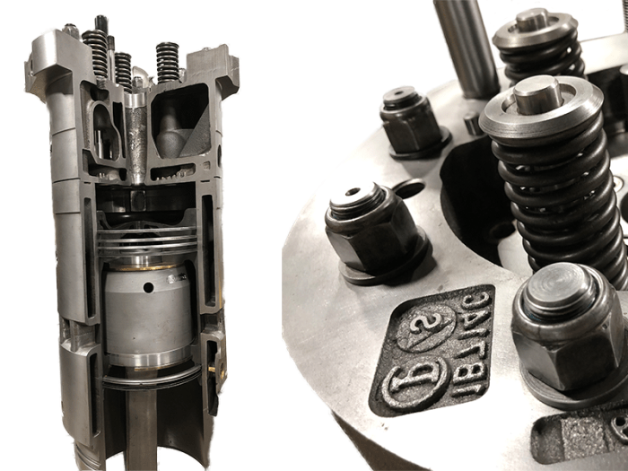
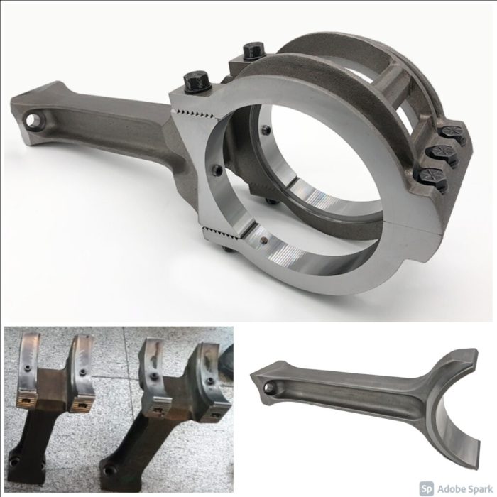
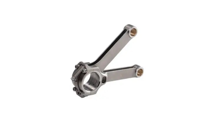
Delving into its design, the fork and blade connecting rod showcases an ingenious combination of strength, durability, and precision. Typically crafted from high-strength materials such as forged steel or lightweight alloys, it comprises a forked end that articulates with the piston pin and a blade end that connects to the crankshaft journal.
The blade section, often of I-beam or H-beam cross-section, provides exceptional rigidity and resistance to bending forces.
Types of Fork and Blade Connecting Rods

Fork and blade connecting rods are categorized into several types based on their design and application requirements. Each type possesses unique features that cater to specific engine configurations and performance demands.
The following table provides an overview of the different types of fork and blade connecting rods, along with their key specifications and applications:
| Type | Features | Applications |
|---|---|---|
| H-Beam |
|
|
| I-Beam |
|
|
| X-Beam |
|
|
| Tubular |
|
|
Materials and Manufacturing Process

The materials used in fork and blade connecting rod production are primarily determined by the intended application and performance requirements. Here are some of the commonly used materials:
- Steel: Steel is a widely used material for fork and blade connecting rods due to its high strength, durability, and resistance to wear. Alloy steels, such as chromium-molybdenum steel (4140), are often preferred for their enhanced strength and toughness.
- Aluminum alloys: Aluminum alloys offer a combination of lightweight and high strength, making them suitable for applications where weight reduction is crucial. They are also corrosion-resistant and have good thermal conductivity.
- Titanium alloys: Titanium alloys are known for their exceptional strength-to-weight ratio, corrosion resistance, and high-temperature performance. They are commonly used in high-performance applications, such as in racing engines.
The manufacturing process of fork and blade connecting rods typically involves several steps:
| Step | Equipment |
|---|---|
| Forging | Forging press |
| Heat treatment | Heat treatment furnace |
| Machining | CNC machining center |
| Finishing | Grinding, polishing, and honing equipment |
Design Considerations
Fork and blade connecting rods are crucial components in internal combustion engines, requiring careful consideration during the design process to ensure optimal performance and durability. Key factors that influence design decisions include strength, weight, and durability, with specific applications often driving specific design optimizations.
Strength
The strength of a fork and blade connecting rod is paramount, as it must withstand the significant forces generated during engine operation. The connecting rod experiences tensile, compressive, and bending loads, and its design must ensure it can handle these forces without failure.
Weight
Reducing the weight of the connecting rod is desirable for improving engine performance, as it reduces the inertial forces acting on the crankshaft. However, weight reduction must be balanced against strength requirements to ensure the connecting rod can withstand the operating loads.
Durability
The durability of the connecting rod is critical for long-term engine reliability. The connecting rod must be able to withstand wear and tear over extended periods, including high temperatures, corrosive environments, and repeated stress cycles.
Applications of Fork and Blade Connecting Rods

Fork and blade connecting rods find extensive use in various industries, primarily in applications involving reciprocating motion and power transmission. Their unique design makes them suitable for handling high loads and stresses.
Automotive Industry
In the automotive sector, fork and blade connecting rods are crucial components of internal combustion engines. They connect the piston to the crankshaft, facilitating the conversion of reciprocating motion into rotary motion. The fork and blade design provides strength and durability, enabling them to withstand the high pressures and temperatures encountered during engine operation.
Aerospace Industry
Within the aerospace industry, fork and blade connecting rods are employed in aircraft engines, particularly in reciprocating engines used in smaller aircraft and unmanned aerial vehicles (UAVs). Their ability to handle high loads and stresses makes them well-suited for the demanding conditions of aircraft propulsion systems.
Manufacturing Industry
Fork and blade connecting rods are also utilized in various manufacturing processes, such as reciprocating compressors and pumps. In these applications, they facilitate the conversion of rotary motion into reciprocating motion, enabling the transfer of fluids or gases. Their robust construction ensures reliable operation under heavy-duty conditions.
Case Studies
One notable example of the successful implementation of fork and blade connecting rods is in the development of high-performance engines for Formula 1 racing cars. Engineers have optimized the design of these connecting rods to minimize weight while maintaining strength and durability.
This has resulted in improved engine efficiency and overall performance.Another case study involves the use of fork and blade connecting rods in the design of reciprocating compressors for industrial applications. By utilizing advanced materials and manufacturing techniques, manufacturers have created connecting rods that can withstand extreme pressures and temperatures, leading to increased compressor efficiency and extended service life.
The fork and blade connecting rod, an essential component in engines, is designed to convert reciprocating motion into rotary motion. Its significance extends beyond engineering, as it finds a parallel in the court of the gentiles diagram , where the Gentiles were connected to the inner court through an intermediary space.
Just as the connecting rod enables the seamless transfer of power, so too does this diagram illustrate the connection between different realms.
Maintenance and Inspection

Regular maintenance and inspection of fork and blade connecting rods are crucial to ensure their optimal performance and longevity. Neglecting these practices can lead to premature failures, reduced efficiency, and potential safety hazards.
Maintenance and inspection procedures involve several steps, including:
Visual Inspection
- Thoroughly examine the connecting rod for any visible damage, such as cracks, dents, or excessive wear.
- Inspect the bearing surfaces for any signs of pitting, scoring, or excessive play.
- Check the bolt and nut connections for proper tightness and security.
Dimensional Inspection
- Measure the length and diameter of the connecting rod to ensure they meet the specified tolerances.
- Inspect the bearing clearances and ensure they are within the recommended range.
Functional Testing, Fork and blade connecting rod
- Perform a dynamic test to check for any abnormal vibrations or noises.
- Monitor the connecting rod’s temperature during operation to identify any potential issues.
Maintenance Intervals and Inspection Criteria
| Maintenance Task | Interval | Inspection Criteria |
|---|---|---|
| Visual Inspection | Monthly | No visible damage, excessive wear, or loose connections |
| Dimensional Inspection | Annually | Length and diameter within tolerances, bearing clearances within range |
| Functional Testing | As needed | No abnormal vibrations, noises, or excessive temperature |
Question Bank
What are the key design considerations for fork and blade connecting rods?
Strength, weight, durability, fatigue resistance, and cost are among the crucial design considerations for fork and blade connecting rods.
What are the different types of fork and blade connecting rods?
Fork and blade connecting rods come in various types, including H-beam, I-beam, and tubular connecting rods, each with unique features and applications.
What materials are commonly used in fork and blade connecting rod production?
Steel alloys, such as 4340 and EN24, are commonly used for fork and blade connecting rod production due to their high strength, durability, and machinability.